
Modeling for 3D Printing: Wall Thickness, Bevels & Voxels
Author: Arndt von Koenigsmarck · Last reviewed August 2026
Modeling your own objects for 3D printing calls for some different priorities than modeling for a render or an animation. A shape that looks flawless on screen can print badly, and a shape that would never survive an animation rig can print perfectly. This guide covers what actually matters when modeling for 3D printing, from wall thickness and Phong shading limits to bevels, voxels and designing parts that assemble cleanly. It is part of our larger guide on Cinema 4D for 3D printing.
How printing changes your modeling priorities
The mesh structure of a model plays only a minor role in printing. Unlike objects meant to deform in an animation, you do not need even edge loops or uniform subdivision density, and it does not matter whether you use triangles, quadrilaterals or n-sided polygons (n-gons).
What does change is how the surface is interpreted. Unlike rendering, 3D printing cannot use Phong shading, the smooth shading that makes low-polygon surfaces look rounded on screen. The printer uses the actual polygon geometry, so a surface that looks perfectly smooth in the viewport can come out noticeably blocky. Because of this, curved and rounded areas need a sufficiently high level of subdivision. This matters even more with resin printers, whose resolution is far higher than that of traditional FDM (filament) printers, so any coarseness in the mesh shows up more clearly.

Programs like Cinema 4D display objects with smooth shading by default, but this does not change the real polygon density. The actual geometry, shown on the right, can be far coarser than it looks. Printing always uses the real polygon structure.
Wall thickness and load-bearing capacity
When you model for print, think about how strong the part needs to be. A certain minimum thickness is required for a printed object to be stable, and this is especially important for large objects printed in several sections, where the join needs enough wall thickness or bonding surface to hold together, depending on the size, weight and expected stress of the assembly.
Minimum wall thickness by process
As a rule of thumb, wall thickness should scale with your printing process. For FDM, design walls at least twice the nozzle diameter, so with a common 0.4 mm nozzle, aim for 0.8 mm or more, and go thicker for functional or load-bearing parts (often 1.5 to 2 mm). Resin processes such as SLA and DLP can go thinner, roughly 0.5 to 1 mm, while still curing reliably. Thin walls that print fine on a small test piece often lack the stiffness to resist bending and warping on larger prints, so err on the generous side for anything structural.
Reinforcing bonding surfaces
For a part such as a mask, you can thicken the modeled front surface afterward with the Thicken Generator in Cinema 4D to create a large enough bonding surface. The join itself can then be reinforced, for example by applying a coat of UV resin for extra strength.

For lightweight assembled parts, a small bonding surface can be enough, and it can be reinforced with additional UV resin where needed.
Reducing shear stress with bevels
Sharp transitions between shapes concentrate shear forces and are common failure points. You can improve the load-bearing capacity of these areas by adding radii, and in Cinema 4D this is easy to do after the fact with the Bevel Generator. The generator can be restricted to specific areas, so you can add rounded transitions exactly where they help most.

Rounded transitions can improve the stability of the printed component in that area.
Robust organic shapes with voxels
If your object has organic, flowing transitions, or if you can build it from a few basic shapes and spline curves, voxels are an excellent option. Think of voxels as small cubes stacked in a uniform grid along the X, Y and Z axes. Their size sets the effective subdivision density of the finished object.
You define where the voxels appear by assigning objects to them. In practice you assemble simple shapes, such as cubes, cylinders or spline-based forms, into a rough version of what you want, then decide per object whether it should be added, subtracted or intersected, and set a rounding radius for the transitions. Unlike Boolean operations, voxels are far more robust in practice, which makes them ideal for high-quality, print-ready models.
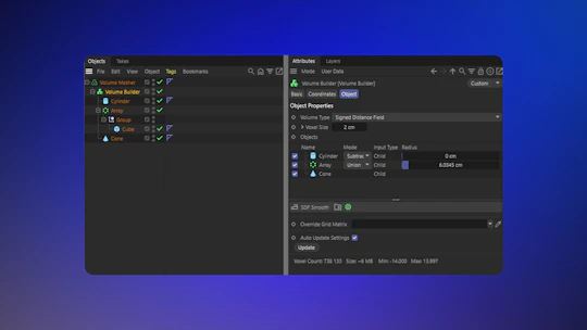


1. A Volume Builder sets the voxel size that fills its child objects, and a parent Volume Mesher generates the actual polygon mesh on top. In its settings you decide for each child whether it is added or subtracted and what rounding radius the transitions get. Everything stays editable.
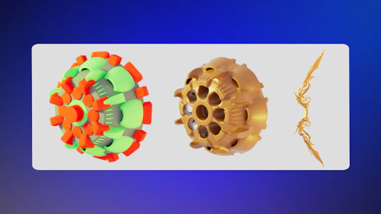
2. Voxels are ideal for the design phase, because combining basic shapes generates complex objects that are automatically watertight and can have natural roundings. Red shapes were subtracted from the cone, green shapes added, and the bow on the right came from a few spline curves.
Designing for assembly
When a design has to be split into parts for printing, plan early for how you will rejoin them, because there is not always room for a dowel or connector. Several joining methods are worth designing around from the start.
Thermal welding
Using a soldering iron, or a device made for melting plastics, you can liquefy the printed filament between two parts so that a stable bond forms as it cools. The plastic inevitably deforms and spreads where it is heated, so that area then needs machining and possibly filling to clean it up.

With a soldering iron or a plastic-melting device, the filament can be liquefied between joined parts, forming a stable bond as it cools. The deformation from heating must then be corrected by machining and filling.
A related method uses a plastic welding device to heat bent wire staples, which are then pressed into the plastic across a joint. For these metal parts to hold securely, the surrounding area should be as solid as possible, which minimizes thermal deformation and reduces cleanup.

Plastic welding devices heat bent wire parts that are pressed into the joint between two molded parts. Solid material in this area helps the metal hold and reduces surface deformation.
For any thermal welding, the relevant areas should be printed as solid as possible, with adequate wall thickness. You can usually set this in the slicer by increasing the number of solid layers at the ends of the part, which lets you press reinforcing elements in from the outside.

In the slicer you can set the wall thickness for solid printing and the number of solid layers at the ends of a part. Since these are usually the joining areas, this simplifies thermal joining methods.
Screws, threaded sleeves and magnets
Integrating magnets, screws or nuts is another reliable way to join printed objects. Unlike gluing or welding, screwing parts together also lets you take the connection apart again, which is handy for transport or replacing a component. Metal sleeves with internal threads, made for exactly this and available in screw-in or press-fit versions, combine with standard screws or threaded rods. In a printed sword, for example, a pommel can hold a threaded sleeve that screws onto a rod running through the hilt, clamping the handle parts together without any adhesive. The recesses for magnets or sleeves are created the same way as for dowels, using the Boolean Generator, as covered in how to add connectors to 3D printed parts.

Metal sleeves with internal threads, available in various sizes, let objects be screwed or clamped together securely without adhesive or welding.
Structural elements and hinges
Support and connecting structures do not always have to hide inside the model. On technical designs, pipes or rods can be part of the visible shape and also serve as connectors between assemblies.

In this model, an aluminum tube serves as the barrel and also connects various components to one another.
Parts also do not always need to be joined permanently. For a hinged connection, you can screw or glue in piano hinges or rod hinges, or model your own joint geometry directly onto the parts.

Here, short strips of piano hinge were glued between adjacent objects to create a flexible connection.
Print-smart tricks worth designing for
Some of the most useful techniques happen at the printer rather than in the model, but knowing them shapes how you model.
With FDM, you can print directly onto fabric. Print two or three fully filled layers, pause, lay a thin, taut piece of fabric over the bed (magnets help hold it flat), then resume. The new plastic bonds to both the fabric and the layers beneath. This works best with thin or mesh fabrics, and with slightly elastic fabric it can even produce wearable, flexible pieces. You can set the pause directly in the slicer so it stops automatically after a set layer, which is also handy for dropping in screws, nuts or magnets mid-print, as long as the print path does not run through the inserted object.

Pausing a filament print after the first layers lets you lay fabric over the print and continue on top of it, bonding the fabric and printed elements together automatically.
FDM prints can also be reshaped with heat after printing, which can simplify modeling for thin objects. A flat piece can be printed quickly without supports, then gently warmed with a heat gun or hair dryer until it is soft enough to bend into shape, holding its new form once it cools. These should ideally be solid-printed parts, and the material should only be warmed until pliable, not until it starts to flow.

These pieces of jewelry were modeled and printed perfectly flat, then shaped into their final form afterward using heat.
Filaments like PLA or TPU can also be used with a 3D printing pen, so you do not always need a printer. The filament is heated in the pen and applied from the tip like liquid ink, which is useful for reinforcing printed elements, joining separate objects, or adding fine patterns and textures that you did not model into the geometry.

A 3D printing pen liquefies standard filament and applies it directly, for example to add to or join printed objects after printing.
Finally, material choice can be part of the design. Flexible filaments such as TPU give a print rubber-like properties, making it more robust against drops and stress, which also helps thin-walled parts. Combined with an internal armature, this enables poseable objects.

This object was assembled from TPU components strung along a flexible aluminum rod, allowing it to be bent into any shape and hold that position.
Frequently asked questions
What is the minimum wall thickness for 3D printing?
It depends on the process. For FDM, aim for at least twice the nozzle diameter, so around 0.8 mm with a 0.4 mm nozzle, and thicker (1.5 to 2 mm) for functional parts. Resin printing can go thinner, roughly 0.5 to 1 mm. Increase thickness for larger or load-bearing prints.
Does mesh topology matter for 3D printing?
Much less than for animation. Even edge loops and uniform subdivision are not required, and triangles, quads and n-gons are all fine. What matters is enough polygon density on curved areas, since printing uses the real geometry rather than smooth Phong shading.
How do I make curved surfaces print smoothly?
Increase the subdivision on curved and rounded areas so the actual polygon mesh is fine enough, because the printer ignores Phong shading. This is even more important on high-resolution resin printers.
What is the best way to strengthen a 3D printed part?
Use adequate wall thickness, add bevels at sharp transitions to reduce shear stress, print joining areas as solid as possible, and reinforce bonds with UV resin, embedded metal, or connectors where needed.
Back to the full workflow: Cinema 4D for 3D printing.